Pressure drop calculator

This Pressure Drop Calculator calculates pressure loss and friction loss in pipes for incompressible fluid flow. It uses pipe geometry, flow rate or velocity, fluid properties, and friction factor to evaluate head loss. The tool is intended for engineering analysis of closed piping systems in water, oil, and gas applications.

Pressure drop calculations depend on the flow regime, which is defined by the Reynolds number. Determine the flow regime using the Reynolds Number Calculator.

Pipe diameter strongly affects velocity and friction loss. Use the Pipe Diameter Calculator to evaluate diameter selection before pressure drop analysis.

Pressure Drop Calculation in Pipes (Darcy–Weisbach Method)

online since 2006
Choose Your Preferred Way to Calculate

Online Calculator

Online pipe flow calculator

Access anywhere. No install needed.

Free Limited Version
🌐 Use Online Calculator

Desktop App

Pressure drop calculator

Desktop full-featured version.

Free Trial Available
⬇️ Download for Windows ⬇️ MacOS / Linux

How Does the Pressure Drop Calculator Work?

Accurately calculating pressure drop in a closed round pipe is crucial for designing efficient piping systems. This calculator provides precise results based on well-established fluid dynamics equations, helping engineers and professionals optimize flow conditions and minimize friction loss.

This online tool determines the pressure loss of fluids flowing through circular pipes by incorporating key hydraulic parameters, including pipe diameter, flow rate or velocity, fluid density and viscosity, pipe roughness.

The calculator applies the Darcy-Weisbach equation, a fundamental formula for quantifying pressure drop and friction loss due to pipe resistance:

Δp = ρfLV22D = 8ρfLQ2 π2D5

This Darcy–Weisbach pressure drop formula is used to calculate friction losses in circular pipes for both laminar and turbulent flow regimes. Here is:

  • Δp = pressure drop (Pa)
  • f = friction factor
  • L = pipe length (m)
  • D = pipe diameter (m)
  • ρ = fluid density (kg/m³)
  • V = velocity (m/s)

Friction Factor Calculation – Colebrook-White Formula

For turbulent flow, the friction factor f is obtained using the Colebrook-White equation, which accounts for friction loss in pipes:

1f = -2.0 log ( kr 3.7065D + 2.5226 Ref )

where: kr = pipe roughness (m), Re = Reynolds number

This implicit equation requires an iterative approach or approximation methods for efficient computation.

Optimize Your Pipe Flow Design

Use our Pressure Drop Calculator to ensure efficient pipeline operation, reduce friction loss, and improve system performance.

Registration

Select a fair price and enable the full service:

  • Switch between metric and imperial units in one click
  • Export calculation results in Word .docx or Excel .xlsx format
  • Preview results on one place and copy/paste it in your favorite text editor
  • Send results back to your email
  • Support the future of this project

And even more... get access to the full set of 19 desktop calculators available for MacOS, Linux or Windows.

Full Year Service

Prepaid Monthly Cost
$3.33/month

Full year $39.95/year

Calculate for:
Select values to input:
Pressures
Flow rates
Coefficients
Flow regime: Flow is turbulent
Pipe dimensions
Fluid properties

Exclusive Online Calculator

Enjoy a distraction-free experience — no ads, no clutter. Just the calculator, pure and focused, like a desktop app.
🔒 Available only to registered users 💡 Choose a fair price and unlock premium access
Use Exclusive Online Calculator

Description

p1 - inlet pressure
Absolute pressure at the pipe start
p2 - outlet pressure
Absolute pressure at the pipe end
Δp - pressure drop
Pressure difference between pipe start and pipe end
q - volume flow rate
Fluid flow rate in terms of units of volume per unit of time
ṁ - mass flow rate
Fluid flow rate in terms of units of mass per unit of time
L - pipe length
Length of a pipe in which pressure drop is calculated
D - pipe diameter
Internal circular pipe diameter
H - channel height
The height of channel for rectangle shaped pipe
W - channel width
The width of channel for rectangle shape pipe
kr - pipe roughness
Pipe internal surface roughness
V - velocity
Flow velocity in terms of units of distance per unit of time
A - area
Internal pipe cross section area
f - friction coefficient
Coefficient of friction for pressure drop due to friction calculation
Re - Reynolds number
Dimensionless number representing viscous versus inertial forces ratio
δ - boundary layer
Thickness of laminar layer formed in turbulent flow connected to pipe wall surface
ρ - fluid density
Mass per unit of volume
ν - kinematic viscosity
Result of fluid particles colliding to each other and moving at different velocities in terms of area per square unit of time
μ - dynamic viscosity
Result of fluid particles colliding to each other and moving at different velocities in terms of mass per square unit of distance and time
K - resistance
Coefficient used for calculation of minor losses due to local resistances in pipe line like bends, tees, reducers, valves, etc.

How to Configure the Calculation

This step-by-step guide explains how to set up all required parameters for calculating pressure drop, flow rate, or internal pipe diameter. Follow the instructions below to ensure accurate and reliable results.

1. Choose the Value You Want to Calculate

Select the parameter that should be computed automatically. The selected value should not be entered manually.

  • Δp — Pressure drop: Calculates pressure loss along the pipe.
  • q / ṁ — Volumetric or mass flow rate: Determines the required flow rate.
  • D — Internal pipe diameter: Computes the optimal pipe size.
2. Enter Pressure Values

Choose which pressure value you want to input. The other one will be determined automatically by the calculator.

  • p₁ — Inlet pressure
  • p₂ — Outlet pressure

Enter only the value you selected.

3. Enter Flow Rate Values

Select which flow rate you want to input. The calculator will compute the other value.

  • q — Volumetric flow rate
  • ṁ — Mass flow rate
4. Enter Fluid Viscosity

Choose whether you will input kinematic or dynamic viscosity. The calculator will convert between them automatically.

  • ν — Kinematic viscosity
  • μ — Dynamic viscosity
5. Choose the Pipe Shape

Select the pipe geometry. Pipe shape affects friction factor and pressure loss.

  • Round pipe: Standard circular pipe with full cross-section flow.
  • Rectangular duct: For rectangular channels with full cross-section flow.

After completing these steps, the calculator will compute the selected parameter using your inputs and fluid properties.

Pump selection calculator – head vs flow performance curve

💧 Pump selection calculator — head–flow curves and speed optimization

Pump Selection Calculator
Pipe network calculator

💧 Pipe Network Analysis — online and free to use!

Network Calculator

Pressure Drop Calculation Guide and Engineering Notes

When Should You Use This Pressure Drop Calculator?

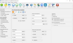
The pressure drop calculator is a powerful tool for calculating pressure loss in pipelines, tubing, and duct systems. It is ideal for engineers, designers, and professionals working with Newtonian fluids (liquids and gases) in closed, round, or rectangular ducts.

This pipe pressure drop calculator applies to incompressible flow, where the fluid density remains constant. It accurately determines pressure loss due to friction, pipe diameter, pipe length, and velocity changes.

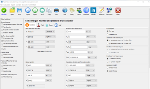
If the fluid is a gas, ensure that pressure changes remain within 5-10% of the initial pressure. If the pressure drop exceeds this limit, use a compressible gas pressure drop calculator for more accurate results.

For gas calculations, the ideal gas law is applied, assuming perfect gas properties to compute unknown values such as pressure, temperature, and density.

This pressure drop in pipe calculator works for both laminar and turbulent flow regimes, making it applicable for various industries, including oil and gas, HVAC, and water distribution systems.

When Is This Pressure Loss Calculator Not Applicable?

  • Compressible Gas Flow: If gas pressure changes exceed 10%, use a compressible gas pressure drop calculator.
  • Non-Newtonian Fluids: The pressure loss in pipe calculator does not support fluids with viscosity changes due to shear rate variations.
  • Multiphase Flow: This pipeline pressure loss calculator is unsuitable for fluids containing solid particles, gas-liquid mixtures, or slurries.
  • Non-Ideal Gases: The piping pressure drop calculator assumes an ideal gas law, making it inaccurate for gases with varying thermodynamic properties.
  • Temperature-Dependent Viscosity: If viscosity changes significantly due to temperature fluctuations, this pressure drop through pipe calculator may not provide precise results.

Key Features of the Pressure Drop Calculator

This pressure drop calculation tool is built to handle a wide range of applications. Key features include:

  • Calculation of pressure drop and flow rate in pipelines, tubing, and ductwork.
  • Supports both laminar and turbulent flows, ensuring accuracy across different flow regimes.
  • Applies to water, air, oil, and gas systems, making it a versatile tool for engineers.
  • Accounts for pipe diameter, pipe length, viscosity, and velocity changes.
  • Works for closed-loop and open-loop systems, ensuring precise results for different designs.

Why Use a Pipe Pressure Drop Calculator?

Accurate pressure drop calculation is essential for designing efficient piping systems. Whether you are working on an HVAC system, an industrial pipeline, or a water supply network, minimizing pressure loss ensures optimal performance and energy efficiency.

Using this pressure loss calculator water can help optimize pump selection, reduce energy consumption, and prevent unnecessary maintenance costs due to high pressure losses.

How to Calculate Pressure Drop in Pipe?

To determine pressure loss in tubing or pipelines, input the following parameters into the pressure drop in pipe calculator:

  1. Fluid Type: Select water, gas, oil, or other Newtonian fluid.
  2. Pipe Diameter and Length: Enter inner diameter and total pipe length.
  3. Flow Rate and Velocity: Specify the flow rate or velocity of the fluid.
  4. Fluid Viscosity and Density: Input viscosity and density based on the operating temperature.

With these inputs, the pressure loss pipe calculator computes pressure drop per unit length and total pressure loss across the pipeline.

For water applications, the water pressure drop calculator or water pressure loss calculator provides highly accurate calculations. If working with narrow tubing, the pressure loss in tubing tool is recommended.

By using the right pressure drop calc, you ensure accurate, efficient, and optimized pipeline performance.

The following example explains why pressure drop calculations are required instead of simple unit conversions when relating flow rate and pressure.

Why GPM Cannot Be Directly Converted to PSI

Many people ask how to convert gallons per minute (GPM) to pounds per square inch (PSI), but a simple conversion is not possible. PSI measures pressure, while GPM measures flow rate. To determine PSI for a given GPM, you need to calculate the pressure drop using fluid dynamics principles.

Pressure Drop Calculator allows you to find the required pressure loss in PSI based on flow rate, pipe characteristics, and fluid properties.

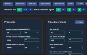
1. Go to the Pressure Drop Calculator

Go to Pressure drop calculator.

2. Enter Flow Rate (GPM)

Input your flow rate in gallons per minute (GPM).

3. Specify Pipe Details

Enter the following pipe parameters:

  • Pipe diameter (in inches or mm)
  • Pipe length (longer pipes create more friction loss)
  • Pipe roughness (depends on material type)

4. Enter Fluid Properties

Input or select the fluid type (e.g., water, oil, air). The calculator considers:

  • Density (ρ) in kg/m³ or lb/ft³
  • Viscosity (μ) in cP or Pa·s

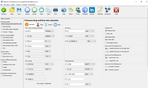
5. Calculate the Pressure Drop

The calculator applies the Darcy-Weisbach equation to determine pressure loss.

6. Understanding the Results

The calculator provides the pressure drop in PSI, which represents the pressure required to maintain the specified GPM flow rate. If your system does not meet this pressure, consider:

  • Increasing pump power
  • Using a larger diameter pipe
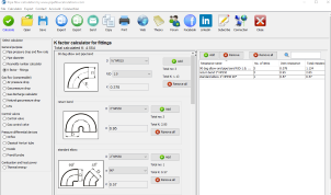
  • Reducing pipe length or minimizing bends

Why You Cannot Convert GPM to PSI Directly

Since PSI depends on pipe resistance, fluid properties, and flow conditions, a simple GPM-to-PSI converter does not exist. Instead, Pressure drop calculator provides accurate results based on real-world fluid dynamics equations.

Desktop App

Pressure drop calculator
Professional-grade pipe flow calculations
Fast. Accurate. Reliable.
Free Trial Available
Win Download MacOS / Linux

Features in desktop app

  • Save/Open multiple results
  • Export to Word and Excel
  • Print results
  • Create list of custom fluid properties
  • Resistance factor K for valves/fittings
  • Pipe surface roughness selection
  • Pipe material selection
  • Gauge vs absolute pressure toggle
  • Compressible isothermal flow
  • Dry air isothermal flow
  • Gas offtake flow
  • Natural gas flow
  • No admin rights required to install

Need a helping hand?

Powered by natural intelligence - NI

calculation_guru

If you need a quick calculation, but you are not still familiar how to use the calculator, you can order calculation service from the calculator developer.

📋 Order calculation service

Watch Examples

Calculator start selection

Read all about available deployments. In any way of utilizing calculator, Internet connection is not required, but nice to have for authentication at least.

Issues and answers

Having problems with calculators usage? Read more about known issues and problems and way to solve it.

Issues and answers